![]()
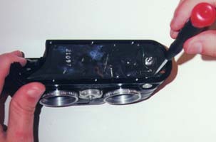
What is Shutter BounceThis is caused by one or both of the shutter blades bouncing off the shutter pad partially reopening or re-closing the shutter (depending on which blade bounces). This typically results in a dark underexposed area on one side of both images. It can be the inverse as well if the second blade bounces and reopens the shutter causing an overexposed area (less common). It's most evident on the highest shutter speed. This can happen over time by the shutter drying out and being compacted. The blades of the shutter are very thin and put a force of thousands of pounds of pressure on the small shutter pad gasket. Over time this hardens the gasket. . What to do about itIf you use ASA 25 film shutter bounce is not noticeable in 99 % of the cameras. If you never use anything faster than 64 you probably wont see it. Shutter bounce can be fixed by replacing the gasket that the shutters ride against. Start by removing the bottom and back, just a few screws. Remove
"Hidden" screws:
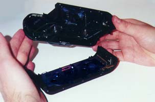
Release shutter. The other mounting screw may be seen at the other end of camera between the front and the frame. With selector knob in A position, remove this screw. Place camera face down on a bench and remove four 1-72 frame mounting screws. Unhook spring from release lever. Unsolder flash connection Unhook shutter release as you remove front.
The gasket is easily visible with the front off. You can replace it with automotive gasket or try putting a thin strip of sorbothane behind the existing gasket. To replace front: Place front assembly in position, hooking release button shaft in release lever, (of movement). Be sure to get flash switch blade between movement plate and release latch
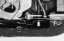
This is tricky, but Important. To do it you must lift front assembly from right side so that you can push the flash contact under the lip of the movement (see Page#3 and #10 for correct position). Be sure release lever spring is free and not being pinched between front and frame. With front assembly entered on butt side of frame, turn selector knob towards B as far as possible. Place assembly on bench and turn selector knob back and forth pressing down lightly until crank assembly enters hole in frame and front assembly is completely seated. Check to be sure selector wire (part 547) has entered slot in selector plate (part 155). Install and tighten the four frame mounting screws. Hook release spring into hole in frame. Replace "Hidden" screws: Turn selector knob to B and release shutter. Re-solder flash connection. Replace Back then Bottom. Part numbers referenced can be found in the online repair manual |
||
|
|